Geometry Generation Tool: Description
The Geometry Generation Tool is a software for geometry creation and
GDML export.
It has been developed by the SPENVIS group of the Belgian Institut for Space Aeronomie.
The program allows the user to interactively build geometries using a number of basic primitives.
Simply by adding these objects to a tree, the 3D geometry is created and displayed.
Created objects can be inspected immediately for corrections or modifications.
The perspective can easily be rotated, panned and zoomed by the user.
Loading and saving of geometries created with the Geometry Generation Tool is provided as well as the export to GDML.
The Java-based program uses the Xj3d library for 3D visualisation.
Interface description
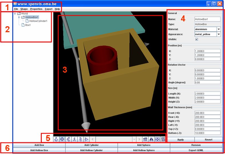
Figure-1: Screenshot of the GUI with frames highlighting the program properties
The screenshot of the user interface shows the program in use and explains its features:
-
Menu bar:
The menu bar offers all functionality by using pop-up menus.
File->Open, File->Save and File->SaveAs provide the im- and export of model geometries in binary format. They will be saved as a .ser file
File->Export will export the geometry in GDML format. It will be saved as a .gdml file.
-
Tree panel:
The tree shows all created objects and their parent-child relation. The current object can be selected by clicking on it.
-
Visualisation panel:
Here is the created structure displayed. Rotation (hold left button & move around) and zooming (using the wheel, in Examine mode) can be performed using the Mouse.
Use the Xj3d-buttons (5) to switch to another perspective.
-
Property panel:
Each object has its own properties like: Material, Appearance, Position, Rotation and Size. They can be changed using the provided widgets in this panel.
The list of materials provides all GEANT4 materials. The Appearance defines a color and transparency. To show an object which is inside another make the outer one transparent.
Changes have to be made in the GUI and submitted by clicking the Apply-button. This will then check if the made input is correct (e.g. no negative thickness).
The current object of the property panel is chosen in the tree panel (2) by selecting it with the mouse. If the user made changes in the property panel and selects
another object in the tree panel a "You changed properties. Do you want to apply the changes?" warning will be issued.
-
Xj3d buttons: On the left side are the options: Fly, Pan, Tilt, Walk, Track and Examine offered.
On the right side are located: "Return to current Viewpoint", LookAt, "Fit to World"
and "Show browser console".
With these options the viewing perspective can be changed. Convenient is the choice "Examine".
-
Action buttons:
Objects can be created by pressing the Add: Box, HollowedBox, Cylinder, HollowedCylinder, Sphere and HollowedSphere buttons.
The assembly of simple objects can create complex geometries.
"Remove" removes the current object and all its children. Think carefully before you remove something as no undo function is provided.
Or save frequently your model using File->Save. The "Export" button exports the model in GDML format.
Parent-child relations
All geometry objects are part of a tree which is shown in the tree panel. This is due to the structure of GDML. The world node defines the space of interest,
and the other objects are located inside.
When creating a structure one can place a child outside its parent. This can be the user's intention or an error.
Only the part of the child that is inside the parent will be used for the actual analysis.
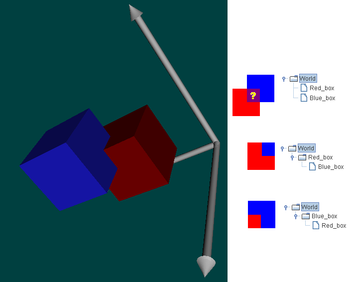
Figure-2: Two boxes with different parent-child relations
From the structure shown in the visualisation panel it is not clear which parent-child relation the objects have.
In principle all children must lay in the volume of its parent, as this is the pattern exported to GDML.
Correct parent-child generation is up to the user as this tool will not check this.
Figure-2 explains the three possibilities.
-
Top:
Red_box and Blue_box are both children of World. It is not clear where the overlapping volume refers to. A GDML error is the result.
-
Center:
Red_box is the parent of Blue_box. Therefore, the overlapping volume refers to Blue_box.
-
Bottom:
Blue_box is the parent of Red_box. Therefore, the overlapping volume refers to Red_box.
Program functionality
Shortly explained, the program offers following functionality:
-
Saving/loading of structures in Java binary format:
Use File->Open, File->Save and File->SaveAs. The structures are saved in JAVA's serialization format *.ser.
-
Creation of geometry nodes:
Geometries can be created using Add: Box, HollowedBox, Cylinder, HollowedCylinder, Sphere and HollowedSphere.
The hierarchy of objects (parent-child relations in the GDML sense) is shown in the property panel.
-
Changing geometry nodes:
Each object has properties which can be changed in the property panel, followed by clicking Apply.
-
Set default shapes:
Use Shape->"Set Shape as Default" to define the the geometry and appearance of the object as default.
To permanently save the object defaults use Properties->"Save Shape Defaults". To reset the defaults use Properties->"Reset Shape Defaults".
-
Export of geometries in GDML / MNL / GMSH format:
Use Export->"Export GDML/MNL/GMSH" or the "Export" button at the lower right corner for GDML export.
3D Geometry Conventions
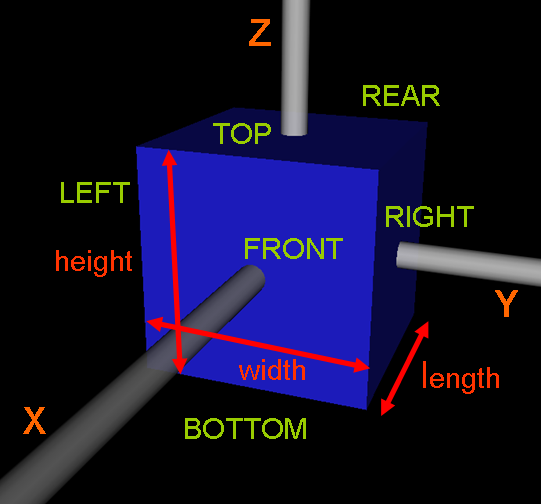
Figure-3: 3D Conventions
Figure-3 shows the used conventions. The length is linked to the X-axis, width to the Y-axis and height to the Z-axis.
The side names Bottom, Top, Left, Right, Front and Rear are important for exporting 2D polygons.
Also mind that the usual length unit is meter [m], but wall thickness is given in millimeter [mm].
Geometry Export
The program provides the geometry export into the following formats:
-
GDML (3D):
The Geometry Description Markup Language (GDML) is a XML based meta-language to define geometries.
This format is used to run GEANT4 based analyses.
GDML exports the entire three-dimansional geometry. Objects are ordered using parent-child relations in a tree.
-
MNL (2D):
This format describes the the objects in a FORTRAN name list. It will be used for the contamination tool of SPENVIS.
All 3D objects are described with 2D polygons. The program exports only the external surfaces of the three-dimansional geometry.
-
GMSH (2D):
Is the geometry definition language of GMSH,
a finite element mesh generator. This format is used for the simulation environment SPIS.
All 3D objects are represented using 2D shell elements. The program exports only the external surfaces of the three-dimansional geometry.
System requirements
The program should execute on every operating system where Java and OpenGL is supported (Windows, Linux/Unix, Mac).
In order to run the program one needs:
-
Java Web-Start, at least version 6.0:
If Java Web-Start doesn't upgrade automatically you follow the link to download and install the
Java SE Runtime Environment (JRE).
-
Geometry Generation Tool:
The package contains several Java packages (*.jar files) which will be downloaded. All together they comprise 14MB.
This download is done once and the files will be saved on your computer. As the program runs in the Java Web-Start environment no installation is required.
-
Internet connection:
The program loads several input files at startup from a web location.
Java Web Start execution problems
Since the new security restrictions of Oracle, one needs to set an exception in the Java properties. This is described in this forum entry.
Last update: Mon, 12 Mar 2018